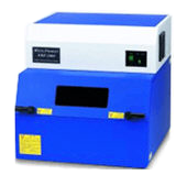
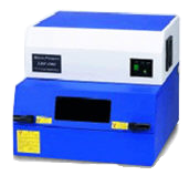
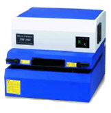
X-Ray System
Model: XRF2000 Model

| Model Name |
XRF 2000H |
XRF 2000L |
XRF 2000PCB |
| Chamber Dimensions |
610 W x 670 D x 600 H |
610 W x 670 D x 490 H |
610 W x 670 D x 490 H |
| Measuring Possible Dimension |
550 W x 550 D x 100 H |
550 W x 550 D x 30 H |
Infinity x 30 H |
| XYZ Displacement Range |
200 W x 150 D x 100 H |
200 W x 150 D x 30 H |
200 W x 150 D x 30 H |
| Max. Use Possible Weight |
5 Kg |
3 Kg |
3 Kg |
Product Feature
| Microsoft Windows: | The XRF 2000 uses Microsoft Windows, allowing multiple tasks to be performed simultaneously. During operation it is possible to review measurements, perform spectrum analysis, and process statistics all while automatically sending the measurement data to Microsoft Excel or other QC programs. |
| Multiple Measurement Capabilities: | The XRF 2000 rapidly and non-destructively measures singlelayer, multi-layer, and composition of alloys. Metal content in plating solutions and qualitative material analysis of alloys are also quickly determined. |
| “Point” & “Measure” Automatic Parts Positioning: | Simply move the cursor to any area of the video image, click the mouse, and the stage moves the part directly under the X-ray beam. Fast, controllable parts positioning is accomplished with ease in seconds. |
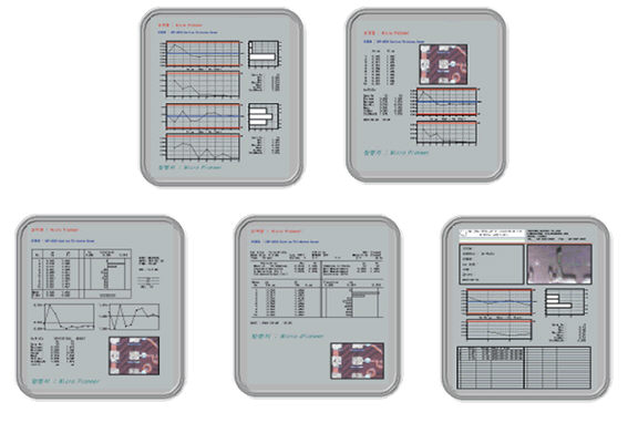
| Custom Statistics Reports: | Instantly preview data in any of the five custom report formats. Measurement data, including statistics, X-Bar & R charts, and even a picture of the sample being measured, can be printed in a variety of layouts. Out-of-tolerance measurements are highlighted in red. |
| Laser Focus Feature: | Precision laser focusing on parts provides the most consistent measurement accuracy possible and eliminates operator error. |
| Stage Forward For Easy Parts Loading: | Opening the chamber door automatically brings the stage forward for fast parts loading and unloading. Precise sample placement is also aided by a positioning laser. |
| Multiple Chamber Models: | Three chambers are available including the H, L, and PCB models. Optional features such as programmable stages, filters, and multiple collimators allow measurement of parts of various sizes and shapes for your specific requirements. |
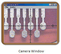
| X-Ray Beam Video Display: | The X-ray beam image is displayed actual size ensuring precise positioning on small parts. |
| Exclusive “Shutterless” Design Extends Tube Life: | Unlike other X-ray systems, the XRF 2000 generates X-rays only while taking measurements. Since the X-ray tube completely shuts off between measurements, there is no need for a mechanical shutter. Less X-ray tube use equals cooler operating temperatures and longer tube life. |
| Chamber Temperature Regulation: | Another first in X-ray design is the exclusive cooling controls which maintain consistent temperature of key system electronics. Measurement stability is further enhanced by the reduction in temperature variation. |
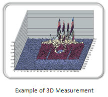
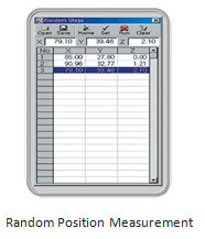
| 2-D and 3-D Plating Thickness Mapping: | Topographic mapping of plating thickness is easily accomplished. The resulting graphic is displayed in color or can be printed for further analysis. Stage programs include both automatic random and constant distance measurements. |
| Automatic X-Ray Beam Alignment: | The Beam Position feature aligns the X-ray beam to the camera image. This prevents measurement errors, unnecessary service calls, or instrument down time due to misalignment. |
| Instrument Service and Support: | Instrument service and diagnostics are simplified by intelligent product engineering and the use of interchangeable components. XRF service, calibration, and technical support is provided by Micro Pioneer SEA experienced staff |
| X-Ray Calibration Standards: | The thickness standards per ISO-17025. Thickness standards for most measurement applications are offered at competitive prices. All thickness standards per ISO-17025 are traceable to the NIST and guaranteed accurate. |
Technical Specification
|
Technical Specification |
||
|
Chamber |
Input Power |
220V AC 50/60 Hz |
|
|
Data Port |
RS – 232 |
|
|
Temperature Control |
Automatic preamp and chamber temperature regulation |
|
|
Focusing |
Precision laser assisted |
|
|
Sample Positioning |
Laser-guided parts placement |
|
|
Safety Circuitry |
Automatic X-ray shut-off within 0.5 seconds, if chamber door opened during measurement |
|
|
|
|
|
Collimators |
Type |
Single fixed or multiple (automatic) |
|
|
Single Fixed |
4, 8, 12, 16 Mils diam. or 2×12 Mils rectangular |
|
|
Multiple Automatic (5 Total) |
4, 8, 12, 16 Mils diam. and 2×12 Mils rectangular |
|
|
|
|
|
Computer System |
Computer |
IBM compatible AT/PC |
|
|
Features |
Windows operating system, CD/DVD drive, and USB ports |
|
|
Monitor |
Flat screen LCD |
|
|
Printer |
Industry standard printer |
|
|
|
|
|
Camera System |
Camera |
Digital, CCD, color, high-resolution |
|
|
Display Image |
Monitor overlay video display |
|
|
Reticle Image |
Software generated target |
|
|
X-Ray Bean |
Actual-size beam displayed by software |
|
|
XRF Beam Alignment |
X-ray beam and camera optics are auto aligned |
|
|
Sample Lighting |
Long-life LED, adjustable |
|
|
|
|
|
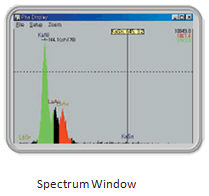
Qualitative Element |
Method |
ROI and peak distance method |
|
Analyzer |
Display |
Color spectrum with element labeling |
|
|
Magnification |
Magnifies/highlights desired items |
|
|
|
|
|
Stage Program |
2-D |
Regular distance parts and surface measurements |
|
|
3-D |
Topographical mapping of plating thickness |
|
|
Random |
Irregular distance parts measurement |
|
|
|
|
|
Multi-Channel |
Channels |
1024 Channels |
|
Analyzer |
Pulse Processing |
High speed using micro-processor |
|
|
Temperature Control |
Automatically regulated |
|
|
|
|
|
X-Ray Source |
X-Ray Tube |
Long life, tungsten target, miniature spot size |
|
|
High Voltage |
0-50kV, oil-cooled |
|
|
Tube Current |
0-1.0 Ma |
|
|
XRF Housing |
Large oil-filled tank encloses both X-ray tube and high voltage |
|
|
|
|
|
Detection System |
Detector |
Proportional counter |
|
|
Filters |
Motorized Cobalt (Ni optional) |
|
|
|
|
|
X-Y-Z Stage |
Operating Type |
Precision, high speed stepper motors with ramped acceleration and cushioned deceleration |
|
|
Stage Positioning |
Mouse or automatic controls �Point and Measure� 2-D and 3-D positioning |
|
|
EZ Loading Stage |
Automatic stage forward by opening/closing door |
|
|
|
|
|
Calibration |
Application |
Single layer, multi-layer, alloy thickness and composition, plus solution analysis |
|
|
Correction Function |
- Density correction |
|
|
|
- Drift correction by reference sample |
|
|
|
|
|
Statistical Analysis |
Statistics |
Mean, maximum, minimum, range, standard deviation |
|
|
Charts and Graphs |
X-bar and range chart, histograms |
|
|
|
|
|
Report Printing |
Reports |
Five (5) custom report formats |
|
|
Previewing |
Instant previewing of reports |
|
|
Customer Heading |
Company name and logo |
|
|
Parts Image |
Sample picture can be printed on report |
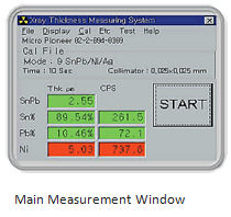
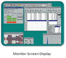
Graphical Display
A Graphical User Interface (GUI) based Measurement Windows enables measurement results to be viewed graphically.
 |
 |
 |
 |
 |
 |
User Friendly Reports Preview data in graphical formats.
Preview data in graphical formats.